
By Kelly Hile
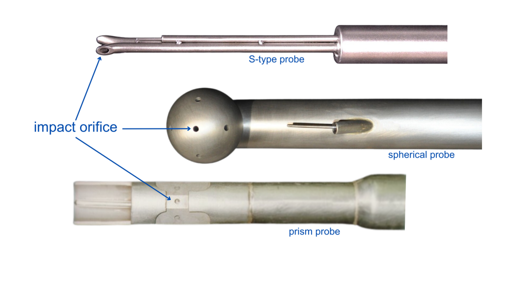
At Airflow Sciences Equipment, we design and manufacture many kinds of probes, from the simple S-type probe to our advanced non-nulling probe. The probes we design use pressure measurements in a flow stream to determine fluid velocity. As such, they are all variations of pitot tubes.
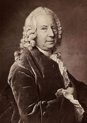
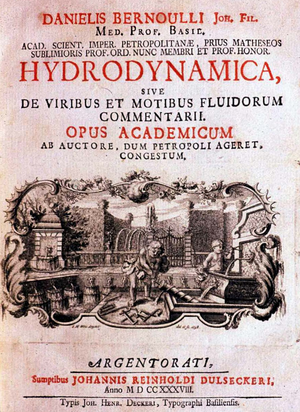
All pressure probes measure velocity in a gas stream by employing Bernoulli’s principle. Daniel Bernoulli first wrote about the relationships between fluid pressure and velocity in his foundational work Hydrodynamica, published in 1738, giving birth to the field of fluid dynamics. In this work, Bernoulli outlined a simplification of the energy equation for a moving fluid, which allowed for a direct correlation to be made between pressure and velocity.
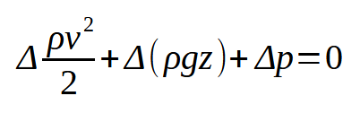
where v is the fluid velocity, g is gravitational acceleration, z is the elevation, p is the fluid pressure, and ρ is the constant fluid density.
Bernoulli’s Equation Explained
The applicability of the relationship between fluid pressure and velocity depends on the flow conditions. Daniel Bernoulli made a few assumptions:
- The flow is steady
- The fluid is not experiencing any work in the zone of interest (e.g. moving a fan or being acted upon by a pump)
- The flow is frictionless (this equation must therefore be applied in a short section of pipe only)
- The density of the fluid is constant (this applies for nearly all liquids but is also reasonable in gases with relatively small pressure variations)
Wherever these assumptions hold, the velocity of a gas stream can be determined using a measured difference in pressure (Δp).
Applying Bernoulli’s Equation to Pressure Probes
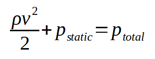
The terms in the Bernoulli equation represent the components of fluid pressure. The pressure referenced in the above equation (p) is the static pressure of the fluid, or the pressure that results from random particle motion and collisions. A fluid that is moving also has a dynamic pressure, expressed as (½)ρv2. Together, the static pressure and dynamic pressure make up the total pressure of a fluid. When elevation changes are minimal (as in most pressure probe flow measurement applications), the Bernoulli equation is often simplified as a relationship between these pressures.

Calculating Velocity
Rearranging this in terms of velocity yields the following expression:
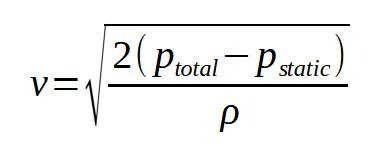
To calculate the velocity, the relationship between two pressure values (total and static) needs to be known, the difference between them being the dynamic pressure. Typically, a probe has a pressure sensor facing the flow that directly measures the total pressure, also called the impact pressure. A minimum of one other pressure orifice is needed on the probe so that dynamic pressure can be determined from the difference.
Probes need multiple, calibrated pressure sensors to determine local flow velocity.
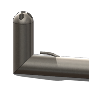
For instance, an S-type probe has one impact orifice and another orifice that faces the wake of the flow. A probe with three or more measurement ports (3D probe) allows for additional information to be gathered from the flow stream, such as the yaw or pitch angle of the flow. Probes need to be calibrated over a range of known velocities to establish the relationship between the secondary (non-impact) sensors and the dynamic pressure. Then the velocity equation, written in terms of the differential pressure of the probe, Δpdiff, is corrected based on a calibration factor, Cp.
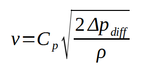
The calibration factor is unique to a probe’s design and geometry.
Non-nulling probe
Alternatively, a non-nulling probe does not require a direct measurement of impact pressure. Instead all five pressure sensors are extensively calibrated in relation to each other such that the velocity can be calculated regardless of the attack angle of the flow on the probe head.
Determining Mass Flow Rates
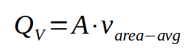
In addition to velocity, test engineers are also interested in determining volumetric or mass flow rates. In practice, a single measurement of the velocity inside a duct or a stack is not enough to fully characterize the flow.
Since the velocity profile of the flow tends to vary across the diameter of the stack, probes are used to sample the velocity at multiple points, gathering a more complete picture of the velocity profile. Sampling locations are typically selected such that each represents an equal cross-sectional area of the stack.
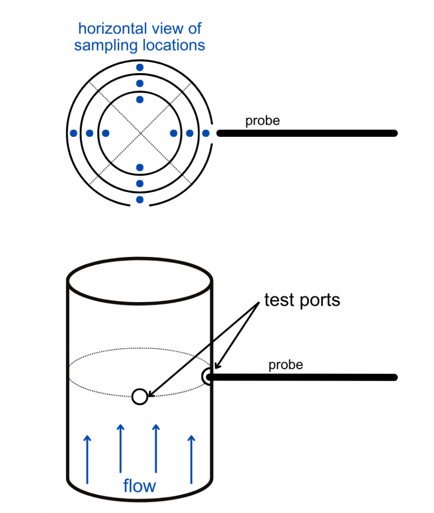
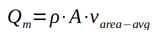
The resulting velocity measurements are averaged based on the cross-sectional areas they represent, or area-weighted. The area-weighted velocity determines the volumetric flow rate when multiplied by the inner cross-sectional area of the stack (A).
The density of the flow stream can be incorporated into this relationship to determine the overall mass flow rate, Qm, as follows.
Determining the density of the flow requires a knowledge of the temperature of the fluid. For this reason, many probes are also outfitted with thermocouples. Density can then be calculated based on the ideal gas law.
Applications of Bernoulli’s Equation
The work of Daniel Bernoulli over 250 years ago remains foundational in all pressure probe measurements. Today, pressure probes are used in wide range of industrial applications, from power generation to food processing. As flow testing experts, we continue to build on Bernoulli’s work as we innovate in the flow measurement field. Over the past 25 years we have been delivering accurate probe designs, time-saving techniques, and automated data collection equipment. Do you have questions about which of our probes is best for your industrial or research application? We can help!